Body mold (pineapple tenor)
Full-depth outside mold that holds the bent sides at the true body outline while the blocks and linings go in, and while the back edge is shaped on the radius dish. Two halves split on the centerline, closed by one bolt at each end, through an added tab at the head (neck) end and an added tab at the tail end. The bolt is horizontal, along the width, through the tab across the split. A bolt in tension resists separation and in shear resists sliding and twisting, so it cannot slide open or lift off the way a swing bar in a 3 mm pocket can under radius-dish scrubbing. Loosening the wing nuts a few turns (without removing the bolts or nuts) relieves the squeeze so the rim slides out vertically. Build it before Session 5. Saw kerf: ripping a solid stack removes a slot as wide as the saw blade — measure your kerf and shim the split faces with stock totaling the kerf (kerf/2 per face, glued flat, trimmed flush to the cavity) before drilling the bolt holes, so total width, cavity width and tab width return to the drawn 12 in, 9.06 in and 4 in. See the drawing PDF, build sequence, for the full kerf step.
Prototype — dish test still pending. Do not build class molds from this guide until a prototype has been tested on the radius dish: close it around a scrap rim, tighten the wing nuts, and scrub hard, checking that the halves do not shift, the bolts do not loosen, and the washers do not dig into the block faces. If vibration loosening appears, add the optional lock washers (in the guide) and retest.
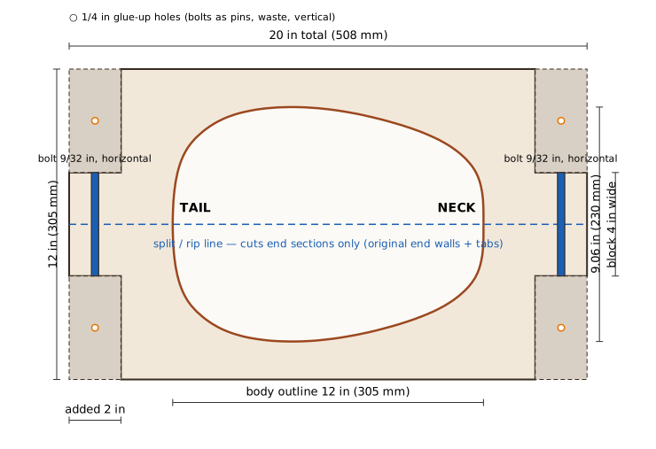
Plan view, TAIL left, NECK right. Stepped footprint: main rectangle 16 × 12 in (original mold, intact) + added tabs 2 in × 4 in at each end, total bounding box 20 × 12 in. Shaded rectangles at the far ends are the cutaways in the added sections only — the original end walls stay full width. Bolt holes (blue rectangles, 9/32 in, horizontal along the width) sit at X = ±9 in, spanning the tab width. Glue-up alignment holes (open orange circles, 1/4 in, vertical) sit at X = ±9 in, Y = ±4 in, in the shaded cutaway waste.
Key dimensions
- Footprint — stepped outline, bounding box 20 in × 12 in: main rectangle 16 in × 12 in (original mold, intact) + added tabs 2 in long × 4 in wide at each end; stack two 3/4 in MDF layers, glued — 1-1/2 in total. No 3 mm laser layer, no pockets, no swing bars. Cut from 24 in × 24 in stock with room to spare.
- Cavity — the body outline, 12 in × 9.06 in (305 × 230 mm), actual size.
- Blocks (added tabs) — one at each end, 2 in long (X ±8 in to ±10 in) × 4 in wide (Y −2 in to +2 in, centered on the split) × 1-1/2 in tall, integral with the original end faces — cut away only the sides of the added sections and leave the central tab. The original end walls (X ±6 in to ±8 in, full width) stay intact.
- Bolt holes — horizontal — 9/32 in clearance for 1/4-20 bolts, axis along the width, at X = ±9 in (tab center), Z = 3/4 in (mid-height). Drilled after the halves are separated, from inside (split face) outward, depth 2 in per half, on a drill press with fence + stop locked (do not move between halves). Do not drill bolt holes vertically from the top face.
- Hardware — 2× 1/4-20 × 4.5 in bolts, 2× 1/4-20 wing nuts, 4× 1 in fender washers (thin). Bolt-length check: block width 4 in + washers (~0.10 in) + wing nut (~0.25 in) = 4.35 in, so a 4.5 in bolt leaves ~0.15 in of thread beyond the nut when tightened — about 3 turns of loosening travel, enough to slide the rim out without removing the bolt or nut.
- Glue-up alignment — 4× 1/4 in holes at X = ±9 in, Y = ±4 in (centers of the added cutaway rectangles), drilled vertically through both sheets clamped together before gluing, with the 1/4-20 bolts themselves as temporary pins (heads on top, no wing nuts, tips hanging free over an overhang — support the stack on blocks/saw horses under the middle so the tips touch nothing). Remove the bolts after curing, before cutting; the empty holes vanish with the cutaways. No separate dowel pins needed; the same bolts are then reused for final assembly.
- Rim seating — lining top-proud 1-1/8 in, dish work bottom-proud about 5/16 in. Wax the cavity walls against glue squeeze-out.
How to use it
- Tighten the wing nuts to close the mold around the rim. To take the rim out, loosen the wing nuts a few turns — do not remove the bolts or nuts — until the squeeze is relieved, then slide the rim out vertically.
- Seat the rim for the job at hand: top-proud (about 1-1/8 in of side above the mold) for gluing the linings, so the clothespins can straddle the side edge; bottom-proud (about 5/16 in below the mold) for shaping the back edge on the radius dish, so the rim edge meets the dish and the mold clears its rise.
- Wax the cavity walls (or line with wax paper) so glue squeeze-out cannot stick the rim into the mold.
Downloads
Mold drawing PDF Cutting file (SVG, true scale)
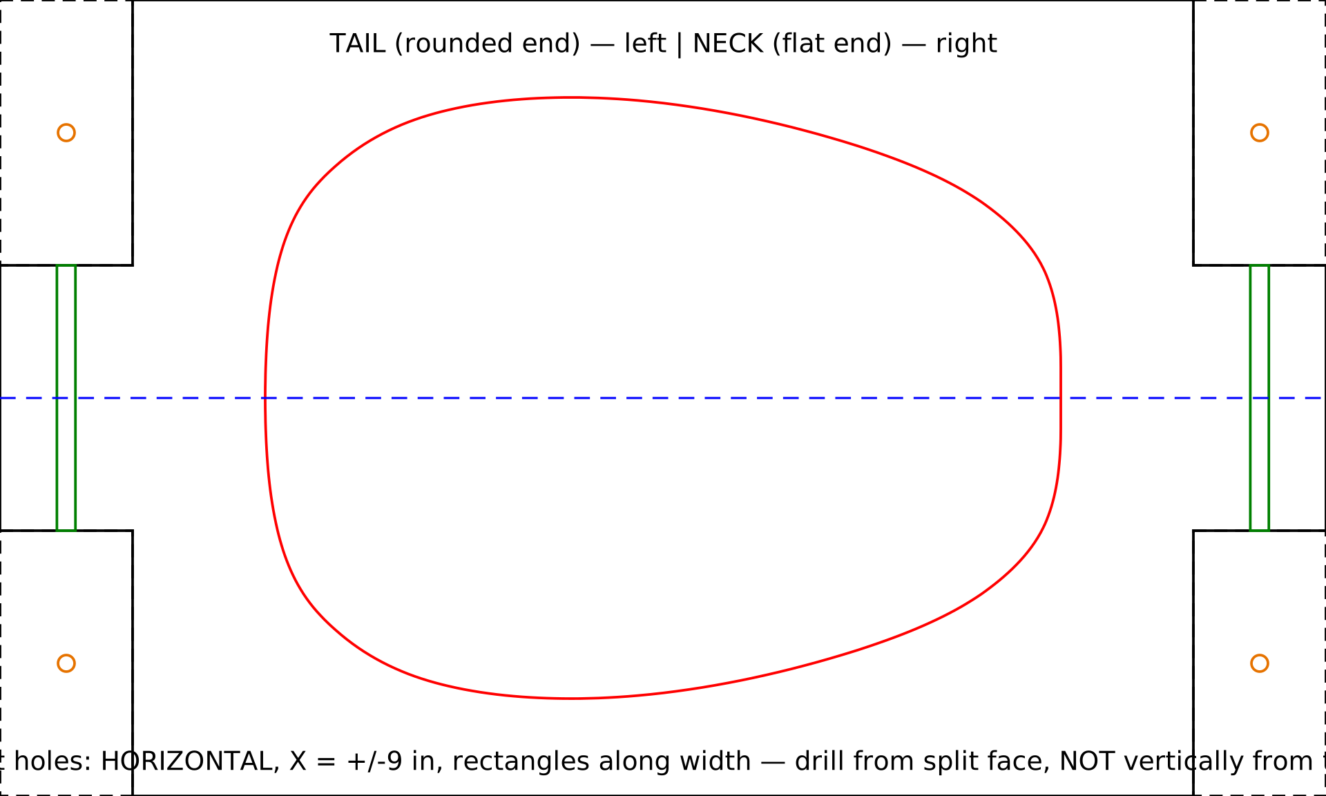
The drawing has the full plan, the bolt section, the hardware, the glue-up alignment, the bolt-hole drilling, the build sequence, and use. The cutting file is true scale in millimeters (marking-out plan only — the mold itself is MDF, cut by bandsaw, not laser-cut from that file).